LDAR programs that treat all components as equally likely emission sources are not wrong exactly, but they are inefficient. Equipment census data and emission factor research from EPA Method 21 studies and OGI survey records consistently shows that certain component types account for a disproportionate fraction of total fugitive emissions from oil and gas facilities. Monitoring resources that are allocated without regard to this distribution find fewer pounds of emissions per hour of monitoring effort than programs that weight their attention toward the higher-risk component categories.
The following five categories are where operators should concentrate their monitoring attention. This is not a complete list of emission sources, and an effective program covers all applicable component types. But if your LDAR program's sensor placement or survey prioritization does not reflect the known distribution of emission rates across these categories, you are leaving detection capacity underutilized.
Control Valve Packing
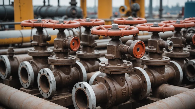
Control valves are the most numerous actuated component type at most gas processing and gathering facilities, and valve packing is the most common single-component leak source in OGI survey data. The packing material around the valve stem creates the pressure seal between the process fluid and the atmosphere. Packing degrades through a combination of thermal cycling, stem friction from repeated actuation, and chemical exposure from the process gas. The degradation is gradual and often produces a small but persistent leak that a walk-down survey finds at the detectable end of the OGI sensitivity range.
High-cycle valves, those that actuate frequently as part of process control, degrade faster than infrequently operated valves. Valves exposed to sour gas containing hydrogen sulfide or other aggressive components degrade faster than those handling dry clean gas. In practice, a small number of control valves at a facility, those that are high-cycle, high-temperature, or exposed to difficult gas compositions, account for a substantial fraction of total control valve packing emissions. Identifying and prioritizing these high-risk valves for more frequent inspection is more effective than applying the same monitoring frequency uniformly across all valves.
Pressure Relief Valves and Rupture Discs
Pressure relief devices are a particularly difficult emission source category because they serve a safety function that cannot be compromised. A PRV that is replaced too aggressively due to a suspected minor leak may create a safety deficit on the line it protects. A PRV that is ignored because accessing it requires a confined space entry and special procedures may be leaking continuously for months between certifications.
Two leak modes are common. The first is simmering: a PRV set close to the process operating pressure where normal pressure fluctuations occasionally push the valve slightly open, allowing small gas releases. This is often misidentified as acceptable operation when it is actually a sign that the valve set point needs adjustment relative to the operating pressure. The second is seat damage: a PRV that has opened during an overpressure event may not reseat tightly afterward, leaving a persistent small leak at the seat. Both conditions are detectable with OGI but are often missed because PRVs are frequently located at heights that are outside the optimal survey angle for handheld camera work.
Open-Ended Lines and Capped Components
Open-ended lines, valved connections that terminate without an in-service connection, are supposed to be capped or plugged to prevent emissions. In practice, cap conditions degrade, plugs work loose, and blinds that were installed years ago develop seal failures that were never followed up because the connection was believed to be isolated. OGI surveys frequently find open-ended lines that field crews were not aware of because the connection was not included in the current equipment register or was believed to be inactive.
This category matters for LDAR compliance because open-ended lines that are emitting are a regulated emission source whether or not they appear in the register. An OGI survey that finds a leaking open-ended line on a segment of piping that is not in the LDAR equipment list creates a documentation problem: the emission has been detected, but the component cannot be assigned a tag number for the repair record. Maintaining a current equipment census that includes all potentially emitting connection points, including historically idle connections, prevents this situation.
Compressor Seal Faces and Shaft Seals
We covered reciprocating compressor rod packing in detail in a separate post on compressor station blind spots. The complementary category for centrifugal compressors is the mechanical face seal on the compressor shaft. Dry gas seals on modern centrifugal compressors are generally reliable under design conditions, but they are sensitive to contamination from liquids in the inlet gas, from process upsets that put the seal faces under off-design load, and from poor seal gas system maintenance that allows the buffer gas supply to run outside specification.
The diagnostic indicator for seal face condition is seal gas flow rate. As faces wear or become contaminated, the seal gas system compensates by increasing supply flow to maintain the designed pressure differential. A seal that is consuming notably more seal gas than its specification suggests developing face wear before the wear has progressed to the point where an OGI camera would see an external plume. Seal gas flow tracking, combined with continuous monitoring near the seal face area, gives earlier warning of seal degradation than either method alone.
Sampling Connections and Analyzer Taps
Sample connections and analyzer tap fittings are small-diameter components with a high leak frequency in OGI survey data relative to their size and a tendency to be overlooked in LDAR monitoring because they are numerous, often accessed only by instrument technicians, and located throughout facilities without a clear spatial cluster. A single facility may have 50 to 100 sample tap and analyzer connection points, ranging from pressurized chromatograph sample loops to manual bottle sampling taps that are opened and resealed regularly.
The seal condition at sample taps degrades through use: a ferrule that is re-tightened dozens of times eventually does not seat correctly. The risk compounds when multiple technicians are servicing the same connection points without a shared record of seal replacements. The result is a diffuse population of low-to-moderate emitters spread across the facility that an OGI survey finds as individual small readings but that contribute meaningfully to total fugitive emissions when summed across the census.
Prioritization for this category should focus on high-pressure connections, connections that are serviced frequently, and connections that are located in areas of poor natural ventilation where accumulation risk is higher. Instrument technician training on proper seal seat technique and a policy requiring seal replacement rather than just re-tightening during any maintenance access can reduce the event rate in this category more cost-effectively than additional survey frequency.
What Prioritization Actually Changes in Practice
A monitoring program that places its highest sensor density, its most frequent survey attention, and its tightest alert thresholds around these five component categories will find more emission-pounds per monitoring-dollar than a uniformly distributed program. This is not a claim that the other component types can be ignored. It is a recognition that risk-weighted monitoring is more efficient than uniform monitoring, and that most facilities have more monitoring investment available to them if it is allocated based on known emission distributions rather than uniform coverage requirements.
The data to support this prioritization already exists in most operators' historical OGI survey records. Looking at which component types appear most frequently in survey findings, and which individual components have appeared in multiple survey cycles, tells you where the system is generating events consistently. That history is the basis for both physical monitoring priority and maintenance investment priority.
Component emission frequencies and relative emission rates described in this article are based on published EPA emission factor studies and industry LDAR program data in the public literature. Site-specific emission distributions depend on equipment age, gas composition, operating pressure, and maintenance history. This article is informational and does not constitute a site-specific compliance assessment. LDAR component coverage obligations are defined by applicable regulations and permit conditions, not by monitoring priority alone.